- English
- Español
- Português
- русский
- Français
- 日本語
- Deutsch
- tiếng Việt
- Italiano
- Nederlands
- ภาษาไทย
- Polski
- 한국어
- Svenska
- magyar
- Malay
- বাংলা ভাষার
- Dansk
- Suomi
- हिन्दी
- Pilipino
- Türkçe
- Gaeilge
- العربية
- Indonesia
- Norsk
- تمل
- český
- ελληνικά
- український
- Javanese
- فارسی
- தமிழ்
- తెలుగు
- नेपाली
- Burmese
- български
- ລາວ
- Latine
- Қазақша
- Euskal
- Azərbaycan
- Slovenský jazyk
- Македонски
- Lietuvos
- Eesti Keel
- Română
- Slovenski
- मराठी
- Srpski језик
Home
>
Products > Hybird Stepper Motor Driver > 2 Phase I/O Control Stepper Driver > Get Enhanced Performance With 2 Phase I/O Control Stepper Driver
Products
- AC Servo Motor
- DC Servo Motor
- Closed Loop Stepper Motor
- Hybird Stepper Motor
- Hybird Stepper Motor Driver
- Closed Loop Stepper Motor Driver
- AC Servo Motor Driver
- Integrated Stepper Motor
- DC Servo Motor Driver
- Screw Motor
- RS485 or CAN or Ethercat Bus type Stepper Driver
- Planetary Reducer
- PLC Controller
- HMI Touch Screen
- Ethercat AC Serco Motor kit
Get Enhanced Performance With 2 Phase I/O Control Stepper Driver
LICHUAN® is Get Enhanced Performance With 2 Phase I/O Control Stepper Driver manufacturers and suppliers in China who can wholesale Get Enhanced Performance With 2 Phase I/O Control Stepper Driver, we can provide professional service and better price for you.
Send Inquiry
Product Description
LICHUAN® warmly welcome you to wholesale Get Enhanced Performance With 2 Phase I/O Control Stepper Driver from our factory in China. Our products have CE certified and currently have a large amount of factory inventory. Lichuan factory have more than 15 years production experience .We are support OEM&ODM ,We will provide you with good service and factory discounted prices. We welcome more distributors to join LICHUAN.
Product Introduction
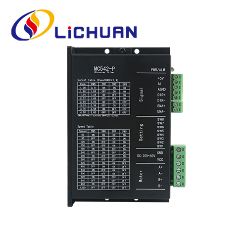
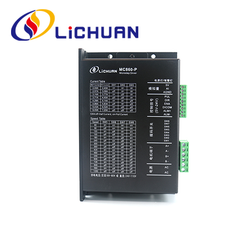
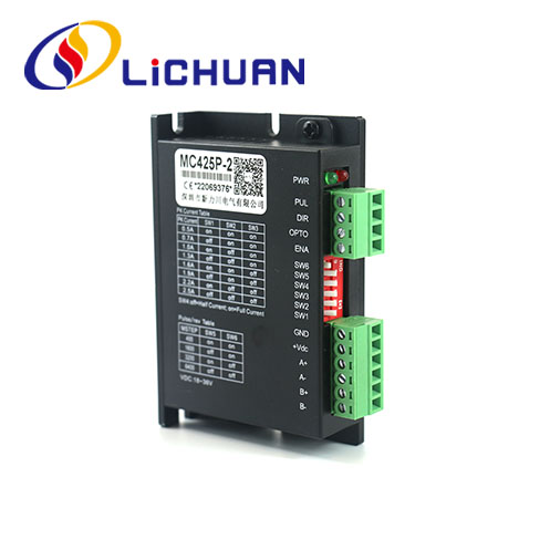
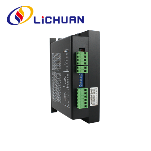
Based on the latest ARM chip technology scheme, the MC542P-2 digital low-voltage step motor drives are generally provided with two-phase 35, 39 and 42 step motor series for achieving excellent medium and low velocity performance. 8 velocity values within 60~600rpm and 8 current values within the rated current range can be set for the application in most small-sized equipment. The control method is simple, the running at a middle or low velocity is very stable, and the drive motor noise is very low. This driver can be match for Nema 23 stepper motor.
Functional characteristics
1. Electrical indexes
● Voltage input range: DC: 20V~50V
● Max. output current: 4.2A
● Insulation resistance: 500M
2. Environmental indexes
● Storage temperature:-20°C~80°C
● Operating temperature:0°C~55°C
● Operating humidity: 90%RH (without condensation)
● Vibration frequency: < 0.5G (4.9m/s2), 10Hz~60Hz (non-continuous operation)
Main applications:
Suitable for automatic equipment and instruments in various motion control fields, such as production lines requiring constant velocity running, as well as feeding and receiving stations;
Technical parameter
● Voltage input range: DC20V~50V
● Maximum peak current:4.2A
● Insulation resistance:500M
● With overcurrent, overvoltage and other protection functions.
● Maximum peak current:4.2A
● Insulation resistance:500M
● With overcurrent, overvoltage and other protection functions.
Environmental parameters
● Storage temperature:-20° ℃~80 ℃
● Operating temperature:0° ℃~55 ℃
● Operating humidity:90%RH(non-condensing)
● Vibration frequency: less than 0.5G(4.9m/s2)10Hz~ 60Hz(discontinuous operation)
● Avoid dust, oil stains, corrosive gases, places with too much humidity and too strong vibration, and prohibit flammable gas and conductive dust
Drive function description
| Drive function | Instructions |
|
Speed range setting |
The four DIP switches SW5~SW8 are used to set the speed range of the drive. There are 16 speed ranges in total. When the user sets the speed, the drive should be stopped first. For the setting of the specific speed range, please follow the instructions on the drive panel. |
| Output current setting | 8 output currents can be set for the Driver through 3 dial switches SW1~SW3. See driver panelinstruction for output current settings. |
| Automatic half -flow function |
Automatic half current function can be set for the Driver through switch SW4. OFF means that quiescent current is set to half of operating current; ON means that quiescent current and dynamic current are the same. SW4 shall be set as OFF for general use to reduce heat generation of the motor and the driver and to improve reliability. About 0.3s after pulse train stops, current will automatically reduce 50%(actual value 55%) and theoretically, heat generation will reduce 65%. |
| Signal interface | PUL+ and PUL- are the motor start control terminals, which support 5V or 24V switching signals; DIR+ and DIR- are the positive and negative terminals of the direction signal; ENA+ and ENA- are the positive and negative terminals of the enable signal. |
| Motor interface | A+ and A- connect to positive and negative terminals of A phase winding of stepper motor; B+ and B- connect to positive and negative terminals, When A and B phase windings are switched, the Motor direction on will be reversed; |
| Power connector | DC power supply, operation input voltage range: 20V~50VDC, 36VDC operation voltage is suggested, power supply shall be higher than 100W. |
| Indicator light | There is 1 green indicator light and 1 red indicator light on the Driver. The green one is power indicator light, it illuminates when the Driver is connected to power supply; the red one is failure indicator light, it illuminates when over-voltage or over-current failure occurs. Red indicator light goes off after failure is eliminated. Failure of the Driver can only be eliminated by re-connecting to power supply and reusing. |
|
Installation Notes |
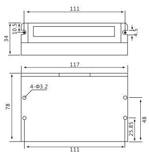
Dimensions of the Driver:117x78x34mm, installation pitch of holes: 111mm. Both horizontal and vertical installations can be selected (vertical installation is suggested). The Driver shall be installed closely against metal cabinet for heat dissipation. |
Parameter setting
The speed range, dynamic and half/full current of the MC542P-2 drive can be set as follows through the 8-bit DIP switch:

Working current setting
| Output peak current | Output average current | SW1 | SW2 | SW3 |
| 1.0A | 0.71A | on | on | on |
| 1.46A | 1.04A | off | on | on |
| 1.91A | 1.36A | on | off | on |
| 2.37A | 1.69A | off | off | on |
| 2.84A | 2.03A | on | on | off |
| 3.31A | 2.36A | off | on | off |
| 3.76A | 2.69A | on | off | off |
| 4.2A | 3.0A | off | off | off |
Installation size (unit: mm)
Speed range setting
| SPD | SW5 | SW6 | SW7 | SW8 |
| 60 | on | on | on | on |
| 90 | off | on | on | on |
| 120 | on | off | on | on |
| 150 | off | off | on | on |
| 180 | on | on | off | on |
| 240 | off | on | off | on |
| 300 | on | off | off | on |
| 360 | off | off | off | on |
| 420 | on | on | on | off |
| 480 | off | on | on | off |
| 540 | on | off | on | off |
| 600 | off | off | on | off |
| 720 | on | on | off | off |
| 840 | off | on | off | off |
| 960 | on | off | off | off |
| 1200 | off | off | off | off |


Lichuan Factory Production Products Machine
-
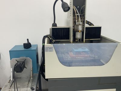
Carving Machine -
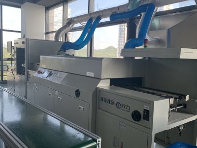
Coating Equipment -
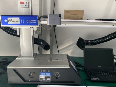
Fiber laster Marking Machine -
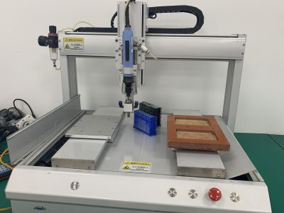
Screwing Machine -
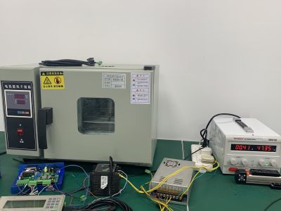
Testing Machine -
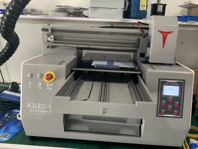
UV Printer
-
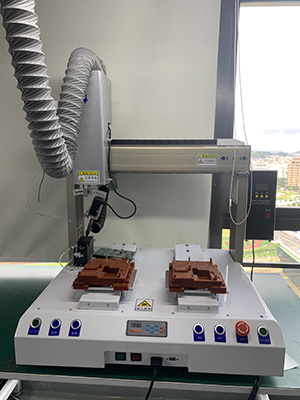
Automatic Soldering Machine -
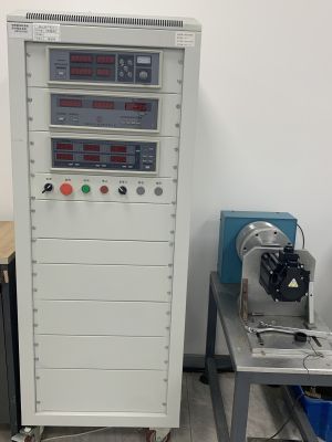
Holding Torque Testing Machine -
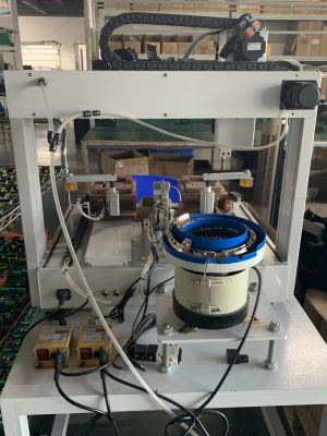
Screw Machine -
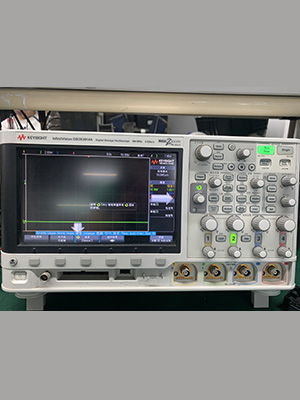
Oscillograph Machine
Industry Applications
-
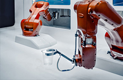
Robotic Arm -
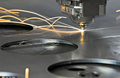
Laser Cutting Machine
-
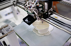
3D Printing -

CNC Machine -
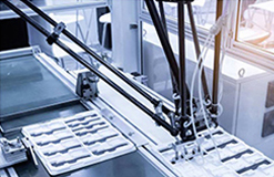
Automatic Assertmbly -
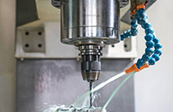
Engraving Machine
Hot Tags: Get Enhanced Performance With 2 Phase I/O Control Stepper Driver, China, Manufacturers, Suppliers, Factory, Customized, Made in China, Cheap, CE, Durable, Quality
Related Category
2 Phase Hybrid Stepper Motor Driver
3 Phase Hybrid Stepper Motor Driver
2 Phase Stepper Driver Mini
2 Phase I/O Control Stepper Driver
Send Inquiry
Please feel free to give your inquiry in the form below. We will reply you in 24 hours.


